Introduction
Many drivers in MAME contain a serial adapter (like RS232) which allows the real system to talk with another system over a serial connection. Unfortunately, none of the implementations of serial adapters in MAME have a true link to the COM (or ttySx) port on the host system - they just write the bytes to a file. While printer ports can well be used with this handling (just print the file with your host system printer later), programs requiring a serial connection usually expect a bidirectional communication, so this is not the way to go.
We need to connect the emulated UART to the host system UART. This can happen in different ways:
- Access the host system UART via operating system calls (like ioctl in Linux).
- Let an external program care for the UART access.
The second option seems more complicated at first sight, but it has one advantage: We can delegate the system-specific interface to the hardware to an external tool, keeping it away from MAME itself.
The solution that I am about to describe indeed relies on an external program. It communicates with it using a socket connection, and over this both components interchange data and control line changes. I will describe the communication protocol below. It should be easy to create other external programs using the same protocol, so we are not bound to a single tool.
The external tool that I am using is TIImageTool which is primarily intended to simplify working with TI disk images and their files. The component of TIImageTool that is interesting for our serial connection is called the Serial Bridge. It can be launched without the rest of TIImageTool by passing the argument BRIDGE:
java -jar tiimagetool.jar BRIDGE /dev/ttyS0 10000
This line opens the serial bridge on port /dev/ttyS0 with a server socket on port 10000. For the rest of this description we assume that the bridge is configured in this way. Note that you must install the RXTX library in your Java environment to get serial port access.
Overall architecture
I achieved the serial connection within the ti99_4a and geneve drivers; the solution should be generic enough to be re-used for all other systems. I will at first show how the overall communication path is set up.
This is the architectural concept:
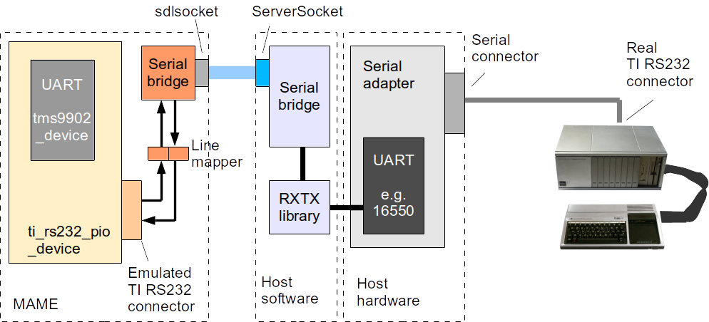
This setup consists of three parts:
- the emulated system, running in MAME; we only show the directly involved component ti_rs232 which emulates the serial interface card.
- the support system on the host providing the serial port access
- the real system which we intend to communicate with; this may also be another PC or a modem.
Apart from the UART, such an interface card may contain a lot of additional circuitry, an on-board ROM, additional control lines to the main system, and more. As we want our emulation to keep close to the real system layout, we also emulate the connector as specified in the schematics.
Not all emulated systems provide a connection that is fully conformant to standards. The TI RS232, for instance, is designed as a DCE device, that is, it looks like a modem. Lines have the same name but opposite direction: CTS and DCD become outputs; DTR is an input. But apart from TI systems, other systems may show similar deviations, which usually require a special cable to be used between them and the other communication end.
This complicates things, since we must somehow operate the PC UART, which offers standardized connections. In particular, we cannot tell the PC serial adapter to operate the DCD line, and we won't get information about the DTR line which is an output on the PC but an input for the TI interface. Thus, a line mapper is used to do the magic of connecting the lines properly. For instance, the RTS line of the UART is connected to the DCD line of the board connector. So our line mapper will change that connection back to RTS or to any other line.
The rules of mapping should not be hardcoded. Different mappings reflect the kinds of cable that are used between the (real) TI and the other system. For instance, while the MYTERM program expects the incoming DTR line to be pulled up by the remote system, the PORT program uses this line for handshaking. A configurable mapper allows us to replace the "virtual cable" as desired.
After the mapper we have a look at the serial bridge on the emulation side. This part should be independent of the driver (although it currently resides in the implementation in file ti_rs232.cpp). Everything before (including the mapper) is at the driver's concern.
The serial bridge on the emulation side has two main roles:
- It transmits outgoing data bytes and line states via sdlsocket.
- It receives incoming data bytes and line states via sdlsocket.
The rules for translating a line state (like RTS, CTS, DTR and so on) into an information unit to be sent over to the other side of the bridge is determined by the RS232 Over IP Protocol which I designed for this emulation. It is similar to the telnet extension for operating modems. I will provide the details of this protocol below.
Serial bridge
The serial bridge is a two-part component whose main task is to encode the data, line, and configuration transmissions from the emulated system into a transmissible format and to send it over the remote connection. The second part decodes the information from the socket connection again.
MAME components
This part belongs to the MAME emulator and is either part of some device (like ti_rs232_pio_device) or may be implemented as an own device. In the outbound direction (from MAME to the outside world) it gets its input from the emulated UART by means of different callback functions (see below). The encoding is contained in the methods transmit_data, configure_interface, output_line_state, and output_exception of ti_rs232_pio_device.
In the inbound direction the serial bridge in MAME decodes the information and passes the data to the UART. These activities are part of the method receive_data_or_line_state, which calls the UART methods tms9902_device::rcv_data, tms9902_device::rcv_break, tms9902_device::rcv_framing_error, tms9902_device::rcv_parity_error, tms9902_device::rcv_cts, and tms9902_device::rcv_dsr.
External component
The external component is realized outside of MAME and may be implemented using any appropriate technology. At this time a working implementation is available as part of the Java-based TIImageTool; it can also be invoked directly when the argument BRIDGE is present.
The external serial bridge component gets data from the socket connection, decodes them, and invokes corresponding functions on the real serial adapter. Java requires a special library (implementing the javax.comm API); a tool written in C or C++ may directly access the adapter (e.g. via ioctl in Linux). Payload data incoming from the socket connection are directly output via the serial connection. When receiving configuration data, the tool reconfigures the interface, and line state protocol units cause the outgoing lines to be cleared or asserted.
In the inbound direction the external bridge component must react to data incoming from the serial connection which are directly forwarded along the socket connection (see the protocol definition). If the real UART senses changes of the control lines, the component must react on these changes (e.g. by employing event listeners) and transmit line state information over the socket connection. The same is true for the BRK condition, which is sensed by the UART of the PC interface. The corresponding event should be handled by the external component and cause a BRK protocol unit to be sent over the socket connection.
Line mapper
As said above, not every interface abides by the standard pinouts, like the TI RS232 interface which is actually a DCE-like interface. With the original systems, this pin order requires special cables; the TI is connected via a direct 1-1 cable with a PC, not with a cross-wired cable. However, the PC's serial adapter cannot change its design, so we have to arrange the lines with a software solution.
The job of adapting the pinout is done by the line mapper. Within the MAME emulator, the function of the line mapper is implemented in the methods map_lines_in and map_lines_out in ti_rs232.cpp. Both functions take a uint8_t value with line states assigned to bit positions and return another uint8_t value as the result of the translation.
Different line mappings may become necessary when there are different numbers of input and output lines or when certain application programs make use of specific pins for handshaking. Within MAME we can handle this requirement by introducing a configuration switch in the MAME menu. With this we can select a mapping as required by the applications in use.
The first option is shown here; I call it the 6-20 (by its wiring). The DSR line is changed into the DTR line. The DSR is fixed to high level, which would now cause the DTR line to go high. This makes sense for attaching a second, real TI system: The DTR output of the PC goes into the DTR input of the TI and unblocks the communication. This is actually the effect of connecting two TIs where DSR and DTR are connected with each other's side.
There is no RTS line on the TI interface: Designed as a DCE interface, the RTS of the 9902 goes into the DCD output pin. Therefore we may decide to link this DCD again with the RTS pin of the PC interface, thus restoring its original function. The CTS line of the TI interface is controlled by setting a CRU bit (a TI-specific internal serial interface, distantly similar to I²C). There is no output line left, so we must drop this line. This way, however, we cannot realize a handshake, neither RTS/CTS nor DSR/DTR.
The full configuration can be seen here:
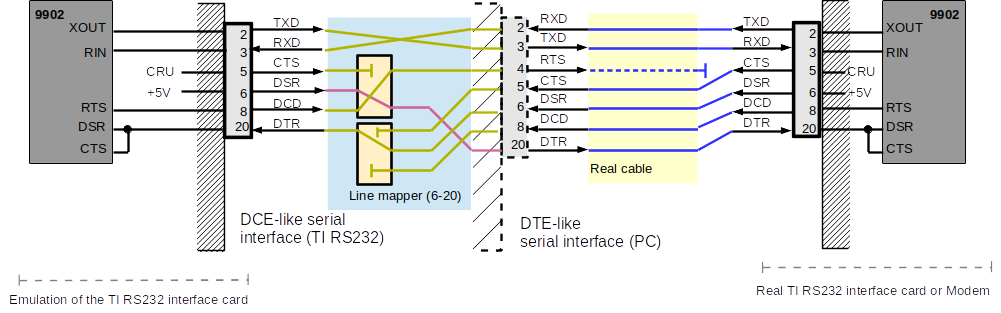
The RTS line from the PC side may be connected to pin 4 on the TI side, but since that pin is not connected, you can as well leave it away. It could, however, be useful when connecting to another PC. The CRU bit on the TI side must be set so that the PC interface is unlocked. If this cannot be ensured, you have to connect the wire to the outgoing DSR line on the right side which is pulled up to +5V. This is just a simple soldering task inside the connector.
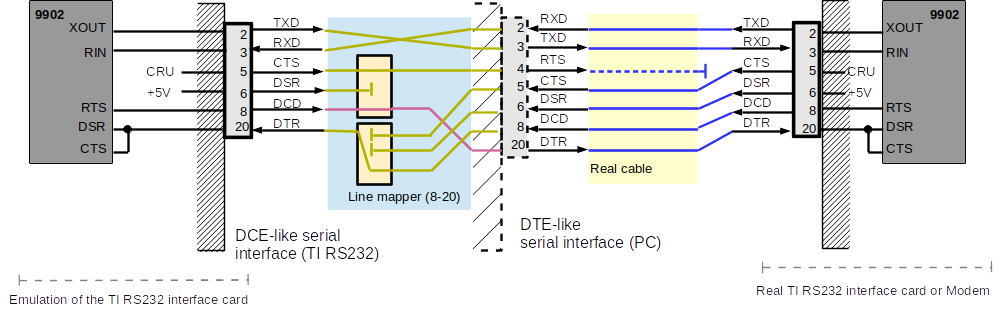
Second option (8-20). In this version we try to make use of the hardware handshake (RTS/CTS) together with a real TI/Geneve on the other side. The RTS line is mapped to the outgoing DTR line, which arrives at the other side at the CTS/DSR input. In the other direction, the RTS line must be connected to the CTS input (and may also be connected to DSR/DCD), which maps it to the incoming DTR line.
Handshake operation: The RTS line is used to halt the other side as needed; it must be asserted on both sides to allow communication. This way, the RTS line is rather a Ready To Receive than a Request To Send line.
Concerning the CTS line, the same is true as said above. If you cannot make sure that it is asserted, switch to the outgoing DSR and leave the CTS pin open on the TI side.
Third option (5-20). This option is similar to the 8-20, with the exception that the handshake is controlled by the CRU line rather than by the RTS line. The advantage is that we can re-use the cable from the first option (6-20).
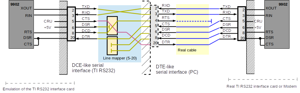
In this configuration the CRU line (which is connected to the CTS output) is used as the new DTR signal. As we are using a 1:1 direct cable, the CRU arrives as the incoming DTR on the other side, which is connected to the CTS and DSR inputs of the UART chip. By controlling this line the remote UART can be suspended and released again. The same works for the opposite direction where the incoming CTS line at the PC interface is routed to the emulated DTR input line, again being mapped to the CTS and DSR inputs of the emulated UART.
Line protocol
At the heart of this work is the protocol between MAME and the serial bridge. The protocol defines the data exchange between the MAME-internal part of the serial bridge and the external part with the following features:
- Transport data in both directions
- Transport settings towards the serial bridge (connection parameters)
- Transport line settings in both directions (handshaking, also including BRK)
- Propagate exceptional states towards the emulator (like BRK or parity error)
As we want to have a full 8 bit data transmission we must find a way to encode line states in a way that they can be distinguished from payload data. This is done in a similar way as we can find it in the TELNET protocol, which means there is a special byte which causes a mode change. Our protocol has two modes:
- Data mode: Bytes transmitted in this mode are normal data bytes, except for the ESC (0x1b) byte.
- Control mode: Bytes transmitted in this mode encode states of control lines or exceptions.
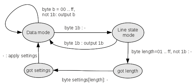
Protocol states
The different states of the protocol are shown in this diagram:
For outgoing communication the sender role of this protocol is taken by the MAME-internal serial bridge component, and the receiver role is the external bridge part. Likewise, incoming communication swaps the roles.
In the normal case the protocol stays in the upper left state; it forwards any incoming byte unless it is the ESC byte. When it gets the ESC (0x1b), it switches to the control mode. If another ESC follows, one ESC is forwarded, and the protocol returns to the data mode. This means that one ESC character can be transmitted by doubling it; a sequence of ESC characters is transmitted by twice the number of ESC bytes.
If the following byte is not ESC, it will be interpreted as a length byte for the sequence of bytes which are now about to follow. The control mode will be left as soon as the announced number of bytes have been received. The receiver applies the settings and returns to the default data mode by itself; no explicit command for returning is used. Typically, these settings concern the communication parameters at the beginning of the transmission, while during the transmission we mainly expect handshake line states. Configuration parameters are only used in outbound direction.
The protocol state machine must be implemented at the external serial bridge and in the emulated interface in MAME. For the TI RS232 interface, the implementation is located in receive_data_or_line_state in ti_rs232.cpp.
Encoding of configuration settings
According to the protocol, the encoding of data and states is simple:
- If a byte b shall be transmitted which is not ESC, send b.
- If ESC shall be transmitted, send ESC ESC.
- If a line state or BRK shall be transmitted, send ESC 1 flags
- If a configuration shall be transmitted, send ESC length config
The flag byte and config bytes are defined by the following tables:
| 0 | 1 | 2 | 3 | 4 | 5 | 6 | 7 | 8 | 9 | 10 | 11 | 12 | 13 | 14 | 15 | 16 | 17 | 18 | 19 | 20 | 21 | 22 | 23 |
|---|---|---|---|---|---|---|---|---|---|---|---|---|---|---|---|---|---|---|---|---|---|---|---|
| 1 | 1 | 1 | 1 | UART ID | Raw 16 bit value of receive data rate | ||||||||||||||||||
| 1 | 1 | 1 | 0 | UART ID | Raw 16 bit value of transmit data rate | ||||||||||||||||||
The other parameters only require 2 bytes.
| 1 | 1 | 0 | 1 | UART ID | * | * | * | * | * | * | data | ||||
| 1 | 1 | 0 | 0 | UART ID | * | * | * | * | * | * | stop | ||||
| 1 | 0 | 1 | 1 | UART ID | * | * | * | * | * | * | parity | ||||
Each configuration command includes four bits for indicating the UART which shall be configured ("UART ID"). The TMS9902 UART gets the 0001. It is necessary to distinguish between different UARTs because UARTs may differ in the way they can be configured. For example, the TMS9902 only knows of three parity settings (none, odd, even) while other UARTs may also support mark and space.
The transmission and receive rate setting depends on the UART. One one hand, the rates vary in a wide range, from as low as 75 baud up to 115200 baud. This would require to use at least 17 bits for their encoding. However, on the other hand, not every rate is valid. This largely depends on the UART. The TMS9902 uses a clock divider to derive the proper rate; parts of the raw value which is passed to it define the divisor, one bit selects between different multiplies, and another bit indicates the clock rate.
As a matter of fact, the actual rate which is used in the TMS9902 does not always match the known, simple numbers. In particular, you cannot set it to 9600 baud; you have to choose between 9434 and 9615 baud, the latter being the better approximation. But the PC adapter that is used in the bridge needs one of the well-known values (at least the RXTX library does not allow for other values). So we have the problem how to guess the baud rate for the PC adapter from this odd number.
Mind that we have different UARTs, and each one may have different approximations. Therefore I chose to not calculate the baud rate within the MAME emulation but to pass the raw settings to the external bridge. Using the adapter ID the bridge has to correctly interpret the values. For the TMS9902 the rate values are 12 bits long, starting at the leftmost bits of the 16 bit field (with four padding zeroes at the right end).
The values for data bits, stop bits, and parity also depend on the adapter. For instance, the TMS9902 uses the values 2 and 3 for 1 stop bit, the value 1 means 2 stop bits, and the value 0 means 1.5 stop bits. Again, let's delegate that to the external bridge.
Encoding of line states and exceptions
| 0 | 1 | 2 | 3 | 4 | 5 | 6 | 7 |
|---|---|---|---|---|---|---|---|
| 0 | 1 | * | * | * | excp | 0 | |
| 0 | 0 | RTS | CTS | DSR | DCD | DTR | RI |
excp: 01 (BRK, Break), 10 (Frame error), 11 (Parity error)
Flags: positive logic (set = 1, clear = 0)
Exceptions like BRK (which is actually a prolonged period of cleared TxD line), framing errors, and parity errors are transmitted as if they had separate lines. If both bits at the beginning are 0, the remaining 6 bits declare the states of the lines. As the signal lines have a direction (output or input), we could have saved some bits and define the line state byte differently for each direction, but we do not want to complicate things, so we assign the lines to fixed bit positions, even if some of them are never used at the same time.
Consequently, this byte may be sent or received. When sent from the emulation, the serial bridge must assert or clear the lines as indicated in the byte (and as applicable for this direction, meaning that it will not be able to set the CTS line, so this is ignored). When received, the byte indicates changes in the line state as sensed by the serial bridge. The emulated interface must set the corresponding flags in the emulated UART (see ti_rs232.cpp, method receive_data_or_line_state, case RECV_MODE_ESC_LINES).
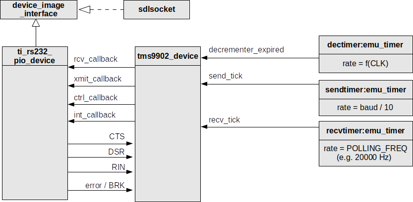
Structure of implementation
The implementation within MAME is shown in the figure below. I will discuss each part of the diagram in detail.
Device image interface and sdlsocket
The external connection is realized using an image device bound to a socket. The other side of the socket connection is the external serial bridge. In order to make MAME set up the socket connection, we need to specify the connection as a parameter.
mame ti99_4a -ioport peb -ioport:peb:slot5 tirs232 -serl1 socket.localhost:10000
The socket prefix creates a socket connection as the image device; the endpoint is specified here as the local host, port 10000. It is possible to use any other host in the network and also any other port, provided that a suitable receiver is running at that location. The serial bridge interfaces to the real PC serial adapter.
ti_rs232_pio_device
This component realizes the serial adapter, in this case the TI RS232 interface card for the Peripheral Expansion Box. The card has two subsystems: One is concerned with interfacing to the emulated computer console which we do not show here. The second subsystem includes the connector to the outside world, the two UARTs (only one shown here), and the wiring of the UARTs to the external connector. The connected serial device image interface can be seen as the emulated external connector.
The card hosts two UARTs, and accordingly, the UARTs get their signals via the card. In turn, the UARTs are an active part of the card, and it is on their initiave to transmit bytes and to sample incoming data and check for exceptional states. The ti_rs232_pio_device component offers 4 functions to the UART (each for the two UARTs):
- rcv[0,1]_callback: Polls the image device for new incoming bytes. The incoming bytes may represent payload data, line states, and exceptions. With every invocation a single byte is queried from the connection. If a multi-byte protocol element waits for input, the rcv_callback must be called multiple times. See below for more details about polling.
- xmit[0,1]_callback: Called when a byte shall be transmitted. In this case the byte is a true payload byte, not a configuration.
- ctrl[0,1]_callback: When a configuration change shall be transmitted to the serial bridge, when the output handshake lines shall be set or reset, or when a BRK shall be sent, this callback is invoked from the UART.
- int[0,1]_callback: The UART may trigger interrupts, in particular when a byte has been received. It then asserts an interrupt line. The board (which hosts the UART) should be designed to handle that interrupt or to propagate it to the computer console.
tms9902_device
This is the emulation of the UART chip; two of them are used on the RS232 adapter. Although it looks like the actual component that communicates with the outside world, it is commonly part of a circuitry on an adapter board, and consequently, not this one but the ti_rs232_pio_device component is associated to the socket device.
The emulated component offers the following methods to the board:
- tms9902_device::rcv_data (RIN): Corresponds to the RIN pin of the UART, with the exception that we pass the whole byte, not its bits, to the UART. This method is called by the board when a byte has been received.
Remember that the board only fetches the next byte from the socket when triggered by the rcv_callback. This seems somewhat confusing at first sight (the UART calls the board to get a byte, and the board in turn calls a method to pass the value to the UART), but the design requires that the socket device is associated to the board, and unlike the real situation we do not have changing levels on the pins without actively fetching them.
- tms9902_device::rcv_cts (CTS): Corresponds to the CTS pin of the UART. Again, when the board receives a change of the CTS line, this method is called to propagate that change to the UART. The UART may trigger an interrupt on that occasion if configured, or it may attempt to send a byte that has been on hold.
- tms9902_device::rcv_dsr (DSR): DSR pin of the UART. See CTS.
- tms9902_device::rcv_framing_error / rcv_parity_error (error): The UART does not offer pins for these features, so these are emulation artifacts. In reality the incoming bits are checked for errors (missing start/stop bits resulting in framing errors, bad parity accordingly causing parity errors) inside the UART, but we are already working on byte level, and any framing or parity error has been detected by the real adapter at the serial bridge.
It is possible for the serial bridge to propagate a framing or parity error by a dedicated protocol unit (see above). Thus we receive this exception value by the board when called via rcv_callback, and then the status flags in the emulated UART are set as though the error had happened inside.
- tms9902_device::rcv_break (BRK): Similar to the error handling, receiving a BREAK state at the real adapter causes a dedicated BRK protocol unit to be passed to the board, which consequently calls this method to set the BRK status flag in the UART.
Three more functions are used as callbacks for timer components.
Timers
The dectimer is an emu_timer instance. It represents an internal timer of the UART which is used in the decrementer mode of the chip. When the timer reaches 0, the TIMELP flag of the UART is set; when the TIMELP has not been cleared before and the timer expires, we have a timer error. This may trigger an interrupt if desired.
The sendtimer is used to regulate the outgoing data rate. It is started in the initiate_transmit function when a byte shall be transmitted over the bridge. We do not handle single bits but complete bytes; this means that the transmission of a complete byte is much faster than in the real device. Application programs commonly query a status bit of the UART to find out whether the last byte has been transmitted completely.
The sendtimer fires after a period of time when the transmission should be over. We assume 10 bits per byte (1 start, 8 data, 1 stop bit), hence the period is 10 / baudrate (in seconds).
The recvtimer is used to implement the polling of the incoming bytes. The rate should be higher than the baud rate (divided by 10). A rate of 20 KHz should allow for a baud rate of up to 200000 baud. The concept of polling deserves a closer discussion below.
Polling
If we want to get bytes from the external connection we have to actively check the incoming connection for available bytes; the bytes will not arrive at the UART by themselves. How fast should this be done?
We could query the interface at the character receive rate (baud rate divided by 10). This has the advantage that incoming bytes are actually arriving at the rate that is defined for this UART.
The disadvantage is that our protocol allows for more than just data bytes. The control lines of the serial connection do not depend on the transmit rates. In principle, changes of the RTS/CTS or DTR/DSR lines may occur at any time during the data transfer. Also, the control bytes (for setting the line states) add to the sequence of data bytes. In an extreme case, if we had changes after each data byte, the actual data transfer rate would be half as high as expected, as we falsely count line state information in the transmission rate.
Consequently, we should choose another way: We could query the interface at a high rate and rely on the sender to deliver bytes at the expected rate.
This alone is not the solution either. Of course, the remote side should set its transmission rate to the same value as the receive rate of the local side, and so the bytes delivered to the emulation should arrive at expected times. There is one particular catch in the concept:
We are using quite a "long" pipe to the other side, including socket connections, which include own buffers. In order to increase thoughput, connections usually buffer incoming and outgoing bytes and release them in bigger chunks. My tests showed that the receiving pipeline stores some bytes in between and releases them in a much higher rate and discrete points of time. While the sending UART delivered bytes at a rate of 120/second (1200 baud), the buffer in between clustered them to small packages with the same average rate, but with a burst of transmission rate within a single chunk. The TMS9902 can only store a single byte, so if we query the socket connection at the high polling rate, we will most certainly cause an overflow in the emulated UART.
The way how this issue was solved is to throttle the reading frequency on the emulation side without reducing the polling rate. This is not a contradiction; we just have to make sure that payload data are delivered at the desired rate. Line state protocol units may be delivered at the high rate. This is the way how it is implemented in ti_rs232_pio_device and tms9902_device.
Read requests are triggered at a high polling rate, and if a data byte has been read, n requests are skipped before the next socket read operation.
This number n is calculated by the emulated UART from the polling rate and the current receiving rate (see tms9902_device::set_receive_data_rate). Hence, if line states are coming in, they are directly processed. If a data byte arrives, a counter is reset, and the next byte is read after skipping n requests. In the implementation we use a value called baudpoll which is added on the counter on each iteration; when it exceeds 1.0, the next byte is read from the socket.
The baudpoll value is passed from the UART tms9902_device to ti_rs232_pio_device with the receive callback function. It must be calculated inside the UART because the adapter board does not know the current receive data rate.
Handshaking issues
The architecture and implementation as described above allows for realizing hardware handshaking. Software handshaking is within the responsibility of the applications that use the serial connection; it is implemented by sending control bytes (X-ON, X-OFF) over the data line.
Hardware handshaking is possible at two levels:
- using RTS and CTS,
- using DTR and DSR.
The difference between both is that RTS/CTS handshaking has immediate effect on the transmission of the UART (a cleared CTS line turns off the transmitter of the UART) while DTR/DSR are handled by interrupts that are signaled to the application.
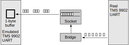
Theoretically, controlling the line state of RTS and DTR and querying the state of CTS and DSR is perfectly possible with the implementation. However, tests suggested that a reliable handshaking is not possible that way: The problem is again related to the buffers in the paths.
Suppose that in the above figure the sender (on the right) transmits a sequence of bytes to the receiver at the left. The receiver wants to pause the sender after every 1000 bytes. When it gets byte number 1000 it clears the DTR line. This change must be transmitted immediately to the sender side. With the buffers in between, this cannot be guaranteed, though. As shown above, the socket connection may have a buffer in the direction from receiver to sender, so the control byte may arrive with a short delay. Even when we could make sure that the change is immediately propagated, the reverse queue (from sender to receiver) may have one byte remaining in the queue.
All this will lead to the effect that there are still a few bytes which can be read at the receiver's side (left) after it cleared the handshake line. The sender must assume that the bytes were validly transmitted before the stop signal; the application on the receiver's side, however, does not expect the extra bytes. These bytes will be lost.
If a byte loss cannot be avoided, handshaking does not make sense.
Variations
There are some possibilities for variations of the concept as shown above. Apart from a completely different approach using library calls to the local serial adapter (which may solve the handshaking issues), the transmission and the code structure can be realized differently.
Using a readable protocol for the serial bridge
The Line protocol is a binary protocol and as such neither readable without its specification nor well expandable. If the protocol shall be re-used with a different kind of interface, a redesign seems unavoidable. Instead one could consider a human-readable protocol which would also enhance debugging.
Protocols of this kind are commonly modeled using XML. That way, an alternative could look like this:
<control>
   <dtr value="T"/>
</control>
0x34
0xfa
0x01
<control>
   <dtr value="F"/>
</control>
This would, however, increase the number of transmitted bytes from 9 bytes (3 bytes for each control sequence: ESC 1 lines) to ... well ... 136 bytes. As always, XML languages are not known for their efficient encoding.
Encapsulation and re-use
The concept as described here should be applicable for a much higher number of systems in the MAME world. Currently, the implementation is part of the tms9902_device and ti_rs232_pio_device classes. It should be possible to design a class that encapsulates the behavior of the complete protocol.
The line mapper will have to stay a part of the system-specific emulation component, since it depends on the particular design of the serial adapter.
It may be a good idea to design the whole protocol as some kind of pluggable device so that alternative realizations become possible.
Evaluation and Conclusions
Good news, the concept does work. I tested it with a real Geneve and the emulated Geneve connected via the local PC's serial adapter. The reliability highly depends on the application program which is used. TELCO, MYTERM, and PORT have been used, and PORT (using an own, optimized serial driver) achieved a reliable transfer at 38400 baud. This was verified by transfering a single large file using the XMODEM protocol.
Errors showed up only when the portions of the file were written to disk; in that phase the incoming bytes were lost which led to retransmissions. It was possible to transfer the MDOS system file (SYSTEM/SYS) of 128 KiB size with no more than 3 retransmitted frames.
Handshaking works in principle. You can demonstrate the effect of clearing and setting DTR or RTS, but it was not possible to maintain a lossless transmission at the points when handshaking was supposed to occur. The reason has been explained above; it does not seem feasible to ensure that (external) buffers are completely empty when a control line state is changed. Anyway, we have two asynchronous streams, one for each direction, and synchronizing them may require considerable efforts, if possible at all.
As byte losses with hardware handshaking are likely to happen, this way of handshaking is not recommended for use, except for demonstration purpose.